No guessing. No blind spots.
At System Surveyor we’re big believers in the value of visual design in physical security and low voltage systems. Both system integrators and corporate/campus technology leaders need modern tools that help them visualize systems as they design and consult about them. That (along with the need for better digital collaboration) was the driving force that led us to build System Surveyor in the first place.
One thing we regularly heard from customers was about area of coverage (AOC). For many customers, System Surveyor has already delivered powerful capabilities for system design and collaboration — including basic AOC information. But there was a dimension missing from our AOC coverage.
We’ll let our customers describe what was missing:
- “Is there a way to draw walls onto the floor plan so I can display true camera viewing areas?”
- “Is it in the works to be able to add walls to the floor plan? It would be helpful to keep the coverage area of cameras from overlapping.”
- “How can you limit camera coverage using walls? Cameras don’t see through walls, but the coverage arc can go beyond what the camera can actually see.”
To address concerns like these, we’re excited to announce our latest feature Boundaries.
System Surveyor Boundaries addresses a practical, real-world concern: security cameras can’t see through walls, poles, or other obstructions. The same goes for motion detectors, Wi-Fi access points, fire alarms, sensors, and more: anything with an area of coverage or field of view may be limited from its theoretical maximum coverage/view because of other objects or obstacles.
3 Reasons Why You Need Easy, Accurate Visual Design
The industry status quo for physical security system design hasn’t exactly been known for accuracy or visuals. So why are we so adamant that easy, accurate visual design is key to better results and (for system integrators) sustainable growth? Here are three reasons.
1. Ensure Accurate Security & IoT Device Coverage
Accuracy is by far the factor with the most practical, real-world implications: a security camera that doesn’t actually cover what it needs to cover is a problem on a half-dozen different levels. It’s a security vulnerability, which means it’s a liability. It could also lead to financial loss, and fixing it takes time and money that could’ve been spent elsewhere. And for the professionals responsible for system design, mistakes like these can harm reputations and relationships with clients and stakeholders.
The same is true for IoT devices: sensors that can’t sense, access control that doesn’t open (or doesn’t lock)— these problems start with inaccuracy in the design phase.
2. Deliver More Professional, Visual System Designs for Better Decisions and Risk Mitigation
Even for experienced professionals, it’s not easy to read a system proposal that’s just a multi-page PDF listing a bunch of devices and parts. And visualizing a proposal like that — translating it from a glorified list to a real-world design — is nearly impossible no matter your skill level.
Compare that to delivering a visual map and system design built on a to-scale digital floor plan. Your visual system design shows exactly where hardware will be installed, exactly what that hardware can do, and even how much it will cost.
Any client, stakeholder, board member, executive or anyone else involved in the decision-making process can look at a visual system design like this and instantly understand at a glance what’s being proposed.
And the results are a win for everybody: the system integrator, corporate or education campus security lead looks more professional, and decision-makers are better informed on the impact of the decisions they’re considering.
3. Avoid Costly Mistakes and Meet Standards
This final benefit is related to the previous two: an accurate visual design helps organizations identify errors or gaps earlier in the process, before parts have been ordered and devices installed. Correcting a problem in the collaborative security system design phase is a matter of an email and a few clicks. Correcting it post-install is an entirely different (and more costly!) experience.
How System Surveyor Boundaries Works: Easy to Use, View & Report
Here’s a high-level overview of how System Surveyor’s newest tool, System Surveyor Boundaries, helps system integrators and corporate/campus technology leaders create even more accurate system designs.
- Start by importing a floor plan or use satellite imagery using our Google Maps Integration.
- Next, drag and drop security devices onto the floor plan, including video surveillance cameras, motion detectors, wifi access points, fire alarms— anything with AoC or a field of view.
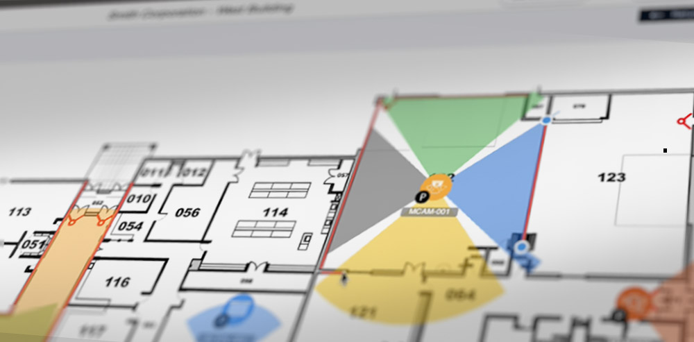
- Select and place the cone or AoC angle and length on your digital floor plan. (Devices from manufacturer partners can provide accurate AoC information automatically.) At this stage, you’ll have theoretically accurate AoC represented on your physical security system design, but those cones will extend through walls and other obstacles, making it difficult to see camera blind spots and similar.
- Next, select the Boundaries icon from the top toolbar. Now you can easily draw in lines to represent walls (or poles or any other real-world obstructions that would prevent the device from covering an area).
- The cones representing field of view or AoC will automatically reshape, showing what the camera or device will “see” after accounting for real-world obstacles.
That’s it— Now you have a more accurate site survey or digital floor plan that can function as your digital as-built during install and on into maintenance. Just a few additional notes:
- Once you’ve completed your system design and verified that the visualization is accurate, you can effortlessly create a PDF version for non-users. Simply navigate to Reports, then Survey Layout. You can add your logo and a legend, then save as a PDF.
- If you’re building a camera system design or IoT or access control system design from scratch, you can move step 4 before step 2. Boundaries will allow you to draw in boundary lines for walls and other obstacles before you’ve placed any devices onto the digital floor plan. Then as you select and place devices (step 3), they will automatically be constrained by your Boundaries, showing a more accurate visual from the start.
- Boundaries works seamlessly in System Surveyor 2.0, including both tablet and web versions.
6 Benefits of Using System Surveyor Boundaries
System Surveyor Boundaries gives security professionals and system integrators a new simple way to show customers and stakeholders the true view or coverage area of devices in an easy-to-understand visual format, now more precise and accurate than ever before.
One of the most significant use cases for this new tool is camera placement optimization. With Boundaries, it’s easy to identify and then share possible blind spots or problem security camera coverage areas due to walls, obstacles and other boundaries. System Surveyor users can implement Boundaries for multiple device types, not just surveillance cameras. The Boundaries feature is highly effective for video surveillance systems, Wi-Fi access points, projectors, motion detectors, and any other type of device that has a field of view or can be disrupted by walls or other obstacles.
Consider these six ways that Boundaries can improve outcomes for System Surveyor users.
- Enhanced Visual Accuracy – Define and visualize the area of coverage (AoC) and field of view (FoV) directly on-site surveys, ensuring better stakeholder engagement and truer alignment with real-world installations.
- Reduced Risk and Costly Mistakes – Visualize accurate area of coverage to minimize the risk of improperly placed cameras and devices, helping users avoid costly rework or blind spot issues post installation.
- Engaging, Professional Deliverables – Provide more polished, professional-looking system designs with precision, boosting client understanding and engagement and bolstering your credibility.
- Time Savings – Show accurate, to-scale designs in one place, accessible in the cloud, without the need to manually modify or update designs in other software programs.
- Better Coverage and Reduced Blind Spots – Ensure all areas requiring surveillance are effectively covered, avoiding blind spots arising from areas that appeared covered despite real-world obstacles, improving overall security and providing peace of mind for clients.
Streamlined Collaboration – Make it easier to communicate camera and device placements and coverage to team members, clients, partners, and any other stakeholders, reducing misunderstandings and errors.
System Surveyor Boundaries Available Now: Try Free
We’re excited to release Boundaries because we see it as a significant value-add to an already valuable solution. System Surveyor Boundaries is live now in System Surveyor 2.0 (including tablet and web). Best of all, it’s available on all our plans — including our free Starter plan — so you can experience the value for yourself.
Sign up now to Try System Surveyor and Boundaries 100% free: Try It Free

Maureen Carlson is co-founder and president of System Surveyor, the leading digital platform for physical-security site surveys and system design. With 25 + years in B2B SaaS and security technology, she leads the go-to-market and operations with a top notch team. Under her leadership, System Surveyor has grown into an industry-defining software used worldwide to streamline system design, enable collaboration, and raise the bar for security and technology professionals. Maureen enjoys building relationships in the industry and user community to build sustainable, high growth business. In her spare time in beautiful Austin, you’ll find her spending time outdoors, on a tennis court, reading or with family and friends.